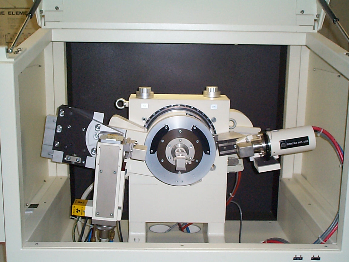
X-ray diffraction apparatus used in this lab. The x-ray source is the box-shaped device on the left, the powder sample is located near the center of the circular section in the middle, and the x-ray detector is the cylindrical device on the right.
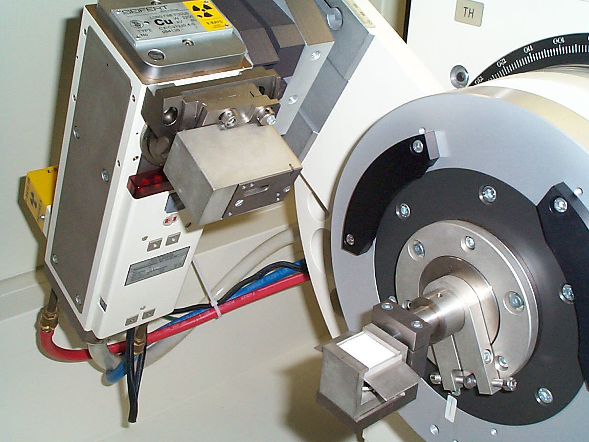
Close-up of the x-ray tube and sample (white powder). Note the heavy cables and cooling lines associated with the x-ray source. Typical operating characteristics are 10's of kV @ 10's of mA. It is a high-power device and must be cooled. The device essentially causes an energetic electron beam to impinge upon a copper target. Copper k-alpha x-radiation is the primary result of that interaction.
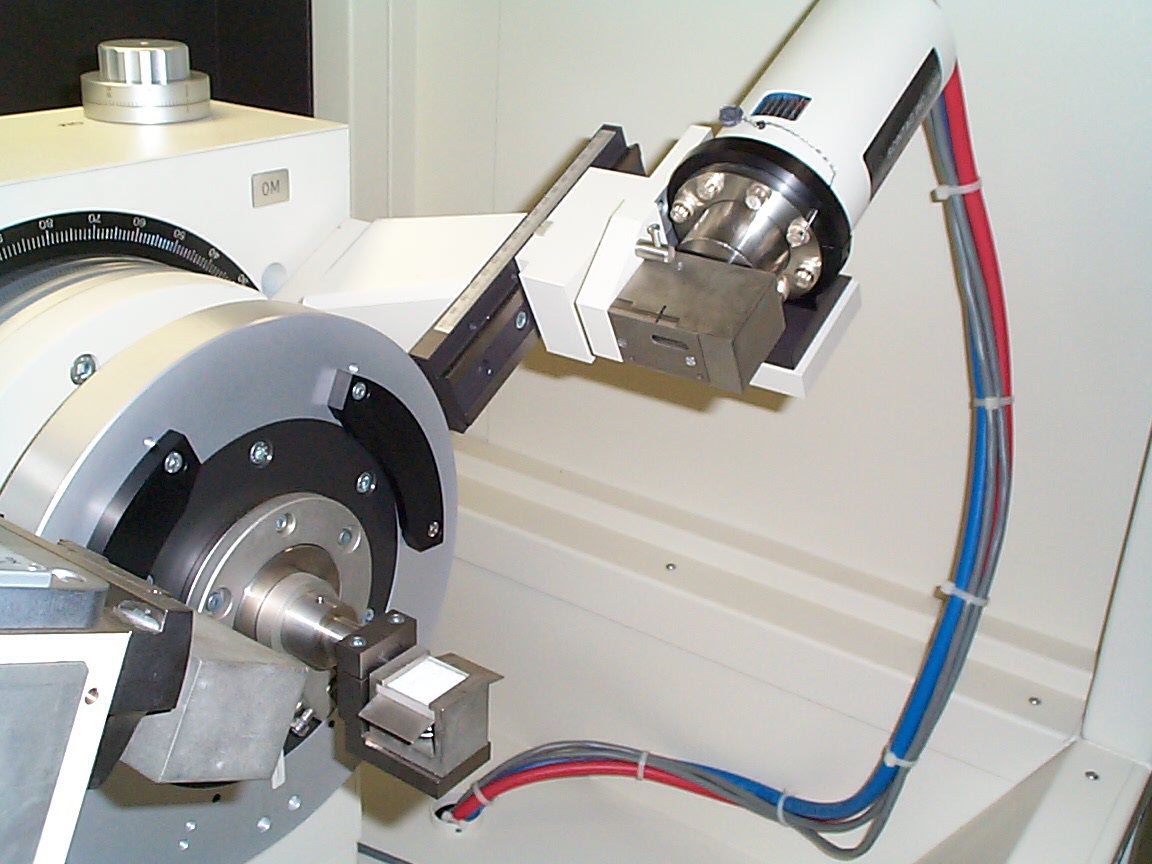
Close-up of the x-ray detector (cylindrical tube with
cables attached). The x-ray detector is a scintillator (barium fluoride)
attached to a photomultiplier tube. I.e., Bragg-diffracted x-rays
interact with barium fluoride, causing it to emit visible light that is,
in turn, detected by the photomultiplier tube. A photomultiplier
(PMT) is a vacuum tube that converts light signals into an electric current.
Typically a PMT will give several hundred thousand electrons out for each
photon in - hence the name photomultiplier. The PMT signal as a function
of angle is the raw data for the resulting x-ray spectra.
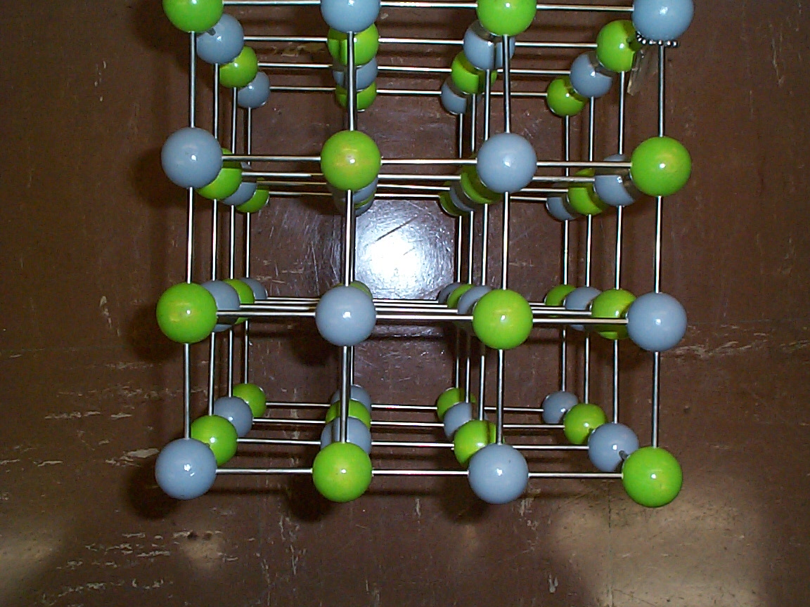
Photo of a model of a simple cubic crystal lattice. The different colors represent different atoms. Various simple crystal planes are shown. Which ones???
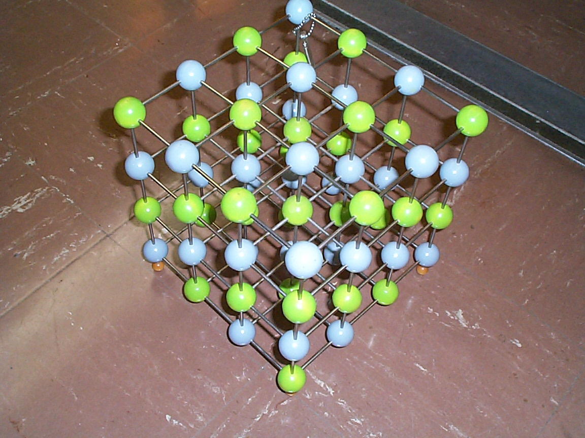
Photo of the same simple cubic lattice model from a different perspective. Other crystal planes are now evident, e.g. all "green atoms," all "blue atoms," alternating. Those planes run diagonal to the cubic structure and have different spacings from the planes most easily visible in the previous photo. What are the Miller indices of the planes shown in this perspective???
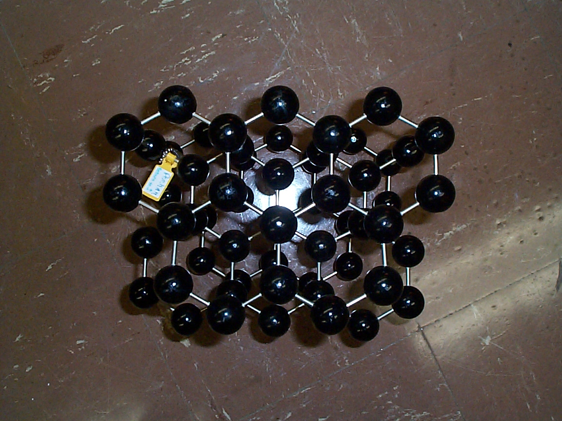
Photo (poor) of the crystal structure of graphite looking down on the hexagonal arrays of carbon atoms. Please note that the carbon atoms at the centers of each hexagon are part of the next plane down from the plane containing the hexagons themselves.
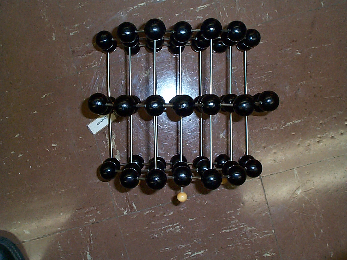
Side view of the same lattice shown in the previous
photo. The planes containing the hexagons easily in the previous
photo have been rotated by 90o. Note the rather large
spacing between the planes that are easily visible in the above photo.
The are why graphite is such a good lubricant.....
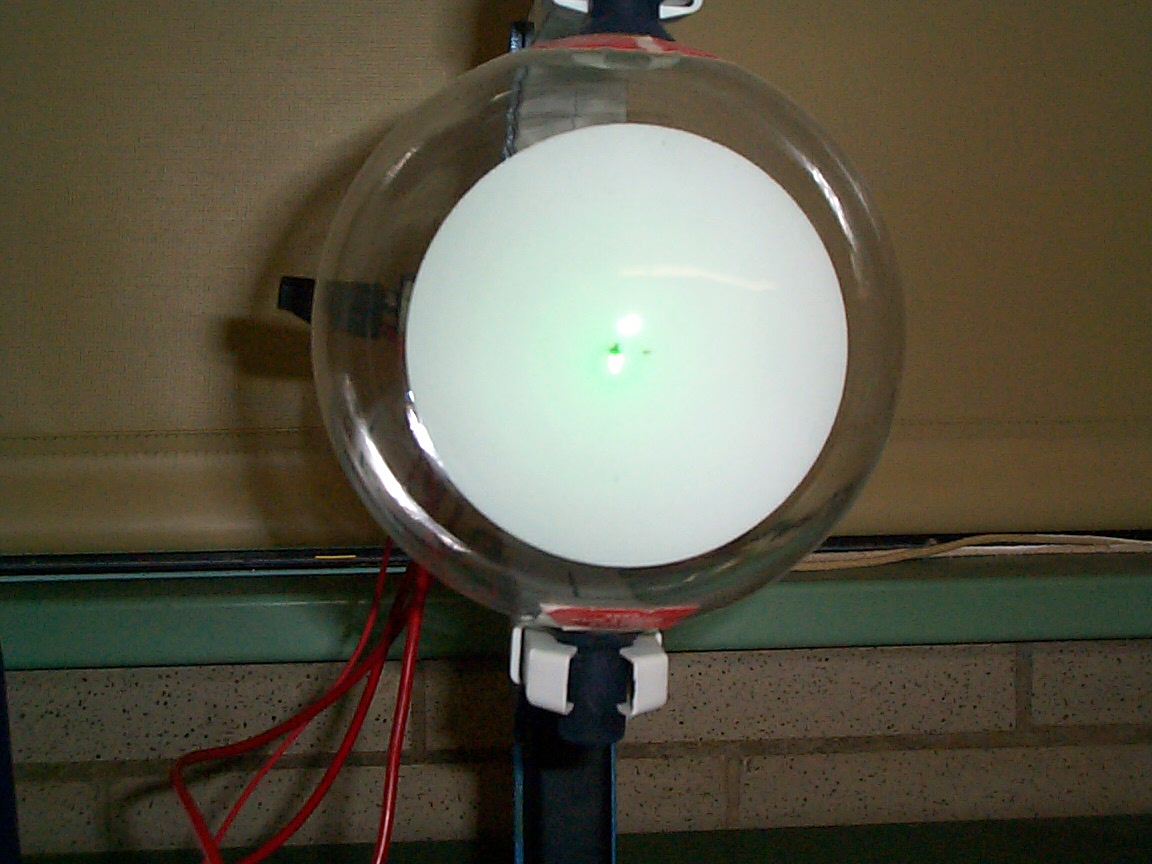
End view of the electron diffraction apparatus used for this lab. The diffraction rings (green) are barely visible in this photo. A good indication of why we must perform our electron diffraction measurements with the room lights off.
| This document was last modified on Tuesday, 19-Sep-2000 17:59:20 EDT
and has been accessed [an error occurred while processing this directive] times.
Address comments or questions to:
|